|
INSTALLATION GUIDE
TABLE OF
CONTENTS
Important safety hints
I. How to install your fence charger
II. Operating instructions for solar installation
III. How electric fencing works
IV. Trouble shooting guide
V. Radio & television interference
VI. Lightning & surge protection
VII. Helpful fence building hints
IMPORTANT SAFETY HINTS!
| 1. |
To reduce risk of electrical shock do not remove
CAUTION cover. Refer to service personnel. |
| 2. |
Never electrify barbed wire! The barbs may
injure animals if they become tangled in the fence. |
| 3. |
Use "1 amp/250V" fuses only. If fuses higher
than 1 amp or lower than 250V are used, they can damage
a fence controller and void your warranty. Fence
controllers that are protected with replaceable fuses
use external fuse holders. If there is no external fuse
holder,
there is no fuse to replace. |
| 4. |
Always disconnect battery-powered fence
controllers from the battery before recharging the
battery. Failure to do so may damage your fence
controller and battery charger, and void your warranty. |
| 5. |
Never run more than one fence controller on
the same fence line at one time. The pulses of short
shock solid state fence controllers will be too close
together and may be hazardous to animals and people. It
will also damage your fence controllers. |
| 6. |
Never alter the design of a fence controller
or substitute components. This could be hazardous
to you and will void the warranty. |
| 7. |
Instruct all persons how to disconnect a fence
controller in case of emergency. Post signs on electric
fences along public roads or near residences. |
| 8. |
Never disconnect wires or approach a fence
during lightning storms. |
| 9. |
"WARNING" Risk of electric shock! Do not
connect an electric fence to any other device such as a
cattle trainer or a poultry trainer. Otherwise lightning
striking your fence will be conducted to all other
devices. |
| 10. |
To reduce the risk of electric shock, an AC line
operated fence controller has a polarized plug (one
blade is wider than the other). This plug will fit in a
polarized outlet only one way. If the plug does not fit
fully in the outlet, reverse the plug, if it still does
not fit, contact a qualified electrician to install the
proper outlet. Do not change the plug in any way. |
| 11. |
Never connect a DC fencer to an AC power
supply. |
| 12. |
Always check your fencer and fence line for
voltage once installation is complete. The fence OK
light will flash when power is on the fence. The fencer
OK light operates continuously with the continuous
current fencers that are equipped with lights. |
INSTALLATION
AND OPERATING
YOUR FENCE CONTROLLER
THE SEVEN SINS OF
FENCE CONTROLLER INSTALLATIONS
|
1. |
An insufficient ground system
for the fence controller. (Refer to Step 2 of the
installation instructions.) |
|
2. |
Stray voltage may occur when the
fence controller ground system is located within 50
ft. of a utility ground, buried water pipe, or
buried telephone wire. (Refer to Step 2 of the
installation instructions and Radio Interference
Section.) |
|
3. |
Inadequately insulated lead-out
wire and jumper wires (wire must be insulated to 20,000V
minimum). (Refer to Step 1 of the installation
instructions.) |
|
4. |
The ground wire is not adequately
insulated and is located 20 ft. or more from fence
controller. (Refer to Step 2 of the installation
instructions.) |
|
5. |
Inferior connections and splices
of the fence wire, ground wire, lead-out wire, and
jumper wires. (Refer to Step 3 of the installation
instructions.) |
|
6. |
Substandard fence wire insulation:
cracked insulators, poor quality insulators, water hose,
plastic tubing, or the use of wood posts without
insulators. (Refer to Step 3 of the installation
instructions.) |
|
7. |
The fence controller is underpowered
for the condition of the fence being energized (i.e.,
rain, snow, ice, vegetation, rusty wire, and length of
fence). (Refer to "How Electric Fencing
Works" in this manual.) |
I. HOW TO
INSTALL
YOUR FENCE CONTROLLER
Grounding Instructions: This controller must
be grounded. If it should malfunction or break down, grounding
reduces the risk of electrical shock by providing a path of low
resistance for the electric current. AC line operated
controllers are provided with a polarized 2-blade attachment
plug for use on a 120-volt circuit. The plug must be inserted
into an appropriate outlet that is properly installed in
accordance with all local codes and ordinances.
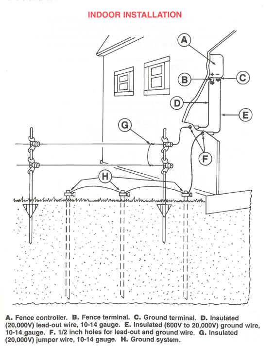
Grounding of this product is provided by a properly installed
ground rod electrically connected to the fence controller output
ground terminal. An internal fault on an improperly grounded
fence controller could result in a risk of high electric shock
currents on the electrified fence.
DANGER - For an AC line operated fence controller, do not
modify the plug provided with the controller if it will not fit
the outlet; have a proper outlet installed by a qualified
electrician. If it is necessary to use an extension cord, use
only a polarized extension cord that will accept the plug for
the unit. Repair or replace a damaged cord.
STEP 1
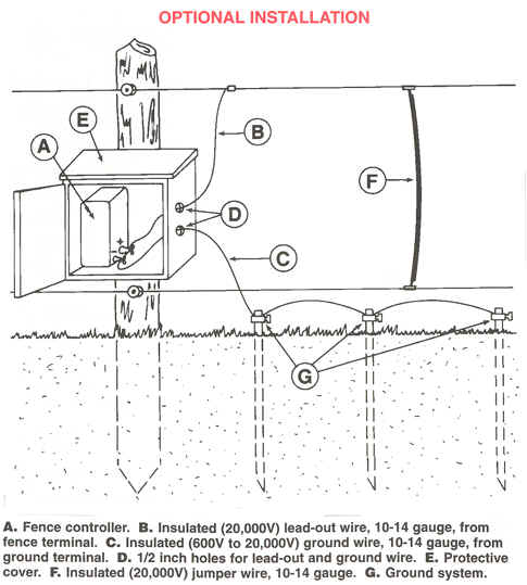
Install your fence controller under cover and protect all
electrical connections from moisture. The fence controller
lead-out wire carries voltage from the (hot) fence terminal to
the fence. A jumper wire carries voltage from one electrified
fence line to another (i.e., gates, buried wire, corners, and
multiple wire fence systems). Use insulted cable that is
manufactured for electric fencing (10 to 14 gauge wire insulated
to 20,000 volts). Do not use common electrical wiring; it is
only rated for 600 volt use.
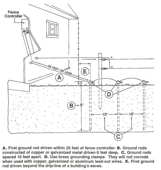
STEP 2
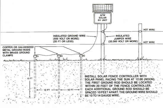
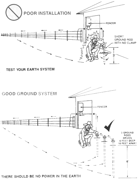
Install at least one 6 ft. galvanized or copper ground rod
within 20 ft. of the fence controller. Use a ground rod clamp to
attach the insulated ground wire to the ground rod (clamp must
bite into rod and ground wire). The ground wire should be 10 to
14 gauge wire and insulated from 600V to 20,000 volts. For best
results, install three ground rods into the earth 6 ft. deep,
spaced 10ft. apart. If possible, install ground rods in areas of
constant moisture.
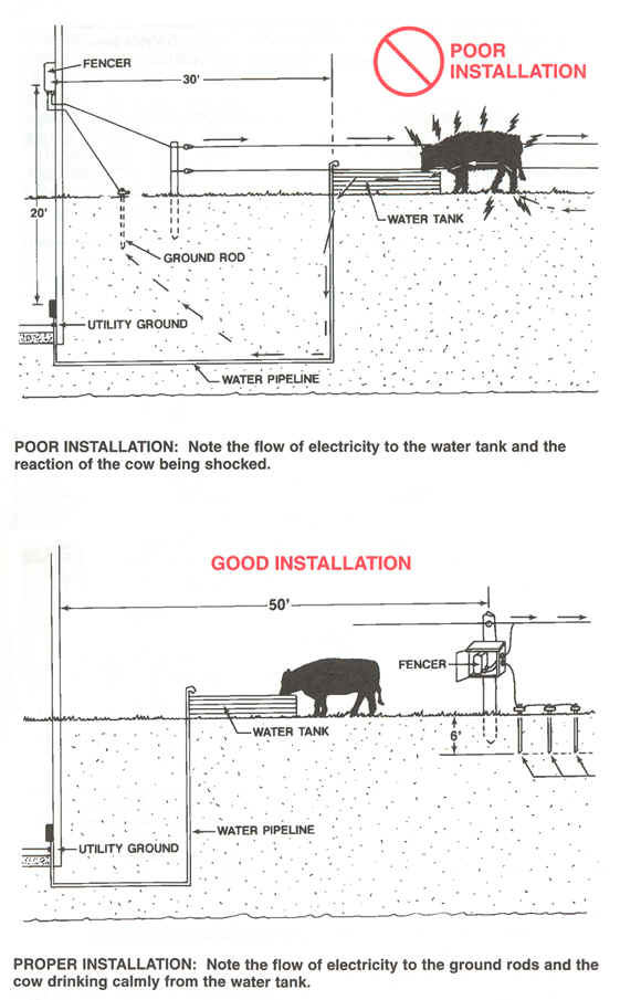
STEP 3
Do not install ground rods within 50 ft. of a utility
ground rod, buried
telephone line, or buried water-line (they may pick up stray
voltage). This is
evident if you receive pulsing shocks from water spigots or
water tanks or if
you hear the pulse of the fence controller in your phone,
television, or radio.
Step 4
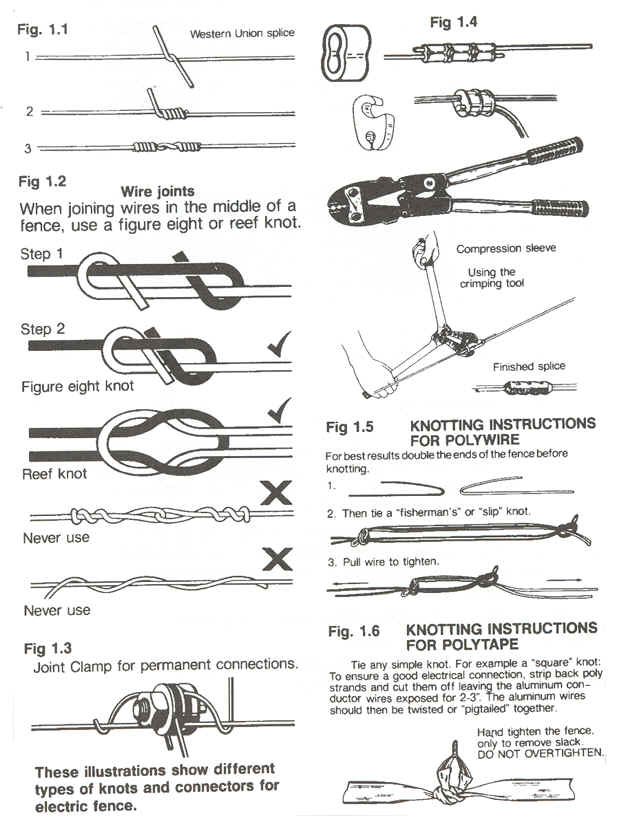
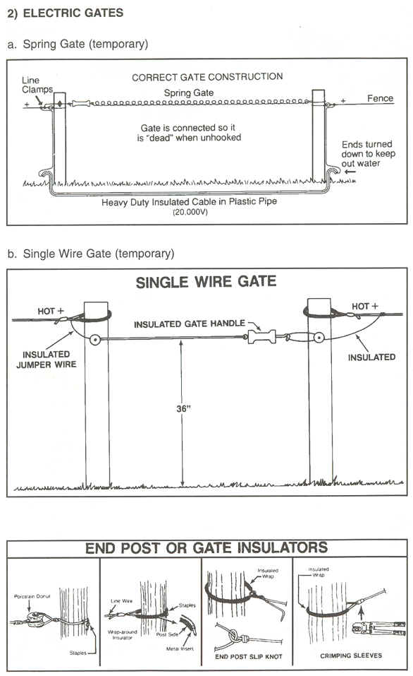
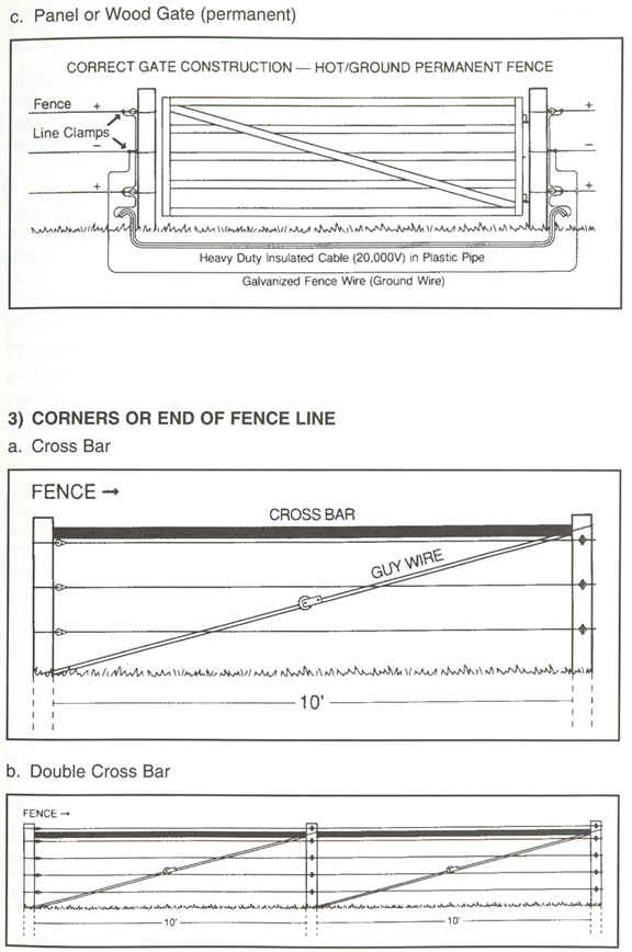
Make good connections, using wire clamps, wire connectors, and
proper splices (refer to drawings). Simply wrapping the wire
loosely causes corrosion at the splice and reduces the power on
the fence. Use high quality insulators, gate handles, and
insulator wrap, with UV (ultra violet) inhibitors for your
fence. If using metal fence posts, make sure fence wires cannot
touch the post. There are specific types of wood posts designed
for electric fence use without insulators.
Illustrations of
different types of knots and connectors for electric fence
II.
OPERATING INSTRUCTIONS FOR THE SOLAR POWERED
ELECTRIC FENCE CONTROLLER
The solar powered fence controller eliminates repetitious
battery recharging and replacement and reduces costs by
utilizing free energy from the sun. Its unique design collects
and stores the sun's energy during both sunny and cloudy weather
conditions. It will retain its full charge through 15 days of
total darkness thereby keeping maximum shock on your fence line
at all times.
This completely portable SOLAR POWERED
fence controller is designed for easy installation. The SOLAR
PANEL is mounted at the proper angle to ensure maximum
year-round energy collection. It is IMPORTANT to mount
your unit in a location that receives full sunlight throughout
the entire day and to fasten it securely to prevent turning and
shifting. Its solid state circuit has excellent high/low
temperature characteristics which are unaffected by changes in
the weather for maximum output voltage on the fence wire.
Installing
Your Solar Powered Fence Controller
STEP 1
Face the SOLAR PANEL towards the noontime sun. Due south
in the northern hemisphere.
STEP 2
Connect the lead-out wire to the fence terminal and connect the
ground wire to the ground terminal.
STEP 3
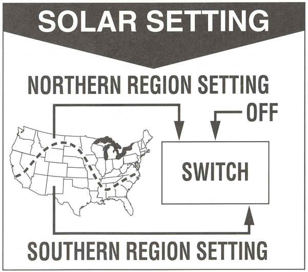
SOLAR REGION SETTING: (For solar fencers that have a solar
setting switch).
Solar fencer installations north of the line
on the solar setting map, have less useable sunlight each day
when compared to installations south of the line.
For optimum performance throughout the year,
installations north of the line on the map should slide the
solar setting switch to the northern region setting (far left
position). Installations south of the line on the map should use
the southern region setting (far right position). If you can't
determine if your installation is north or south of the line on
the solar setting map, use the northern region setting (far left
position). Failure to use the proper solar region setting will
limit the solar fencers battery life and void your warranty.
For solar fencers not equipped with a solar
setting switch, slide the 2 position switch to the on position.
The operating light should flash with each
pulse of electricity that is sent to the fence
FOR BEST PERFORMANCE: After
installing your new solar fence controller, slide the switch to
the "OFF" position. This allows the sun to charge the
solar fence controller battery. Let the solar battery charge for
three full days.
BATTERY MAINTENANCE: Repeat
the above three day charging process each time the fence
controller is placed in storage or taken out of storage. DO
NOT store out of direct sunlight for periods of more
than 3 months without first repeating the battery charging
procedure or the battery may fail.
IMPORTANT:
DO NOT CHARGE THE SOLAR POWERED ELECTRIC
FENCE CONTROLLER BATTERY WITH AN
AUTOMOBILE BATTERY CHARGER. THIS WILL DAMAGE THE BATTERY. A
TRICKLE CHARGER SHOULD BE USED TO MAINTAIN THE BATTERY WHEN THE
FENCE CONTROLLER IS NOT IN USE FOR PERIODS EXCEEDING 3 MONTHS.
CAUTION! DO NOT ALLOW THE BATTERY TO CHARGE OVER 18 HOURS WITH A
TRICKLE CHARGER!
SOLAR PANEL MAINTENANCE: In the instance that battery
replacement becomes necessary be sure to CLEAN the solar
panel. However, under EXTREMELY DUSTY conditions the
solar panel should be cleaned periodically with a soft cloth and
water without detergent or abrasive cleaners. A clean solar
panel will operate at maximum efficiency.
III. HOW ELECTRIC FENCING
WORKS
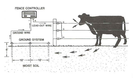
Electric fencing
is a "fear" barrier that uses safe electric shock to deter
animals. In order for an animal to feel a shock, the voltage
produced by the fence controller must be high enough to
penetrate the animal's hair, hide, and hoof. Once the voltage is
high enough to deliver a shock, electricity must travel through
the fence wire. It then flows through the animal that is
touching the fence and into the soil the animal is standing on.
The electricity then travels through the moist soil back to the
ground rods. From the ground rods the electricity flows through
the ground wire that is attached to the fence controller's
ground terminal. The circuit is completed and the animal feels
the shock instantly.
A good ground
system will pick up most of the electricity conducted by the
animal and send it to the fence controller. Poor grounding can
cause interference on telephone lines, in radios, and on
televisions. You may also receive a shock from metal cased
fence controller or ground rod when it is not grounded properly.
In
very dry climates (dry sandy soil) and cold climates (snow
covered or frozen soil) an alternative fence installation must
be used. This fence system implements
the use of a ground wire running parallel to your hot wire. This
ground wire should be grounded every 1,300 ft. with 6 ft.
galvanized
steel
or copper ground rods. This fence installation is no longer
dependent on good soil conditions and will carry the electricity
back to the fence controller's ground system when livestock
contact the hot and ground
wires
simultaneously.

IV. TROUBLE SHOOTING YOUR
ELECTRIC FENCE
Even the best-built electric fences have problems from time to
time. The best time to discover and fix the problem is before
your livestock get loose. Use a volt meter designed to test an
electric fence or a five light fence tester to check the fence
every day. When the voltage drops drastically (Remember:
Although wet insulators from rain or snow will cause fence
voltage to drop, the proper fence controller with correct
installation techniques will perform satisfactorily) take the
following steps. . .
STEP 1
FENCE CONTROLLER DOES NOT OPERATE, CHECK THE
FUSES
| a.
|
Some fence controllers
do not have fuses. Replaceable fuses can be replaced if
there are fuse holders located on the exterior of the
fence controller cabinet. |
| b.
|
If fuses are blown,
replace them with "1 amp/250V" fuses. Plug the fence
controller in. If the fuses blow instantly the fence
controller must be serviced. Should the fence controller
operate for several hours before blowing a fuse there is
a problem with your fence installation, go on to Step 2. |
| c.
|
If fuses are O.K. and
the fence controller does not operate, go on to Step 2 |
STEP 2
CHECK THE POWER SOURCE: Unplug the fence
controller or disconnect the battery clamps from the battery,
before checking power source.
| a.
|
A fence controller that
operates on 115VAC must have a power source ranging from
105VAC to 125VAC. |
| b.
|
A 12 volt battery fence
controller should have a power source of 12 volts
minimum when testing. |
| c.
|
The 6 volt or 6/12 volt
battery fence controllers should have a power source of
6 volts minimum when testing. |
|
Note: for best results
use a deep cycle battery rated at 85 amp hrs or more. |
STEP 3
CHECK THE FENCE CONTROLLER FOR OUTPUT: Use
a volt meter designed to test electric fence controller output.
Ask your local farm store for this product.
If a volt meter is unavailable you can use a
screwdriver as a "gross check" for voltage output. Disconnect
the hot lead-out wire from your fence controller. Do not remove
your ground wire. Using a screwdriver with an insulated handle,
draw an arc between the hot terminal and the ground terminal.
The length of the spark gaps are listed below for your use. This
is not an accurate method to test your fence controller, but it
will indicate whether or not your fence controller's output is
reasonable.
-
The 115VAC solid state fence controllers have
a typical spark gap of 1/8 inch to 1/4 inch
-
The battery & solar fence controllers have a
typical spark gap of 1/16 inch to 3/16 inch
-
The weed chopper fence controllers have a
typical spark gap of 1/32 inch to 1/16 inch
-
The continuous current fence controllers have
a typical spark gap of 1/32 inch to 1/16 inch
If the fence controller output is low your fence
controller should be serviced. If the output is O.K. go on to
Step 4.
STEP 4
IF THE FENCE CONTROLLER OUTPUT AND POWER SOURCE
ARE NORMAL, CHECK THE FENCE INSTALLATION
| a. |
Reconnect the hot
lead-out wire (which was disconnected in Step 3) to the
fence terminal. Then disconnect the lead-out wire at the
fence and check for voltage. If the voltage is good the
lead-out wire is O.K. If the voltage is low, you must
replace the lead-out wire. Use AFW hookup wire
rated at 20,000V. Go on to Step 4b. |
| b. |
Reconnect the lead-out wire and
disconnect all fences that run off the main fence and
check the voltage. If the voltage is low, the problem
lies in the main fence. If the voltage is O.K.,
reconnect fences, checking voltage as each fence is
added. Voltage should remain steady or show a slight
drop until you connect the fence causing the problem.
Then the voltage will drop drastically or the fence will
short out completely.
|
| c. |
Once you determine which
fence or section of fence is causing the problem, walk
the fence line looking for shorts. Look carefully at
corners and gates, and where the fence comes close to
other fences. Pay close attention to insulators and
connections, listen for telltale snapping sounds that
indicate electrical shorting. |
| d. |
Vegetation or rust on the fence is the
most common cause of voltage loss. Even high-power, low
impedance fence chargers lose voltage when enough weeds
and grass touch the fence (especially when wet).
Spraying herbicide under any type of fence is good
management, particularly under electric fence. Rust on
the fence wires acts like an insulator and will not
transfer the electric shock to the animal. If your fence
wire is rusty replace it. |
V. RADIO AND TELEPHONE
INTERFERENCE:
-
The fence controller ground system must be
sufficient-see grounding illustration.
-
The fence controller ground system must be at
least 50 ft. away from the utility ground and buried water
pipes.
-
The fence controller MUST NOT be
connected to the AC utility ground rod or water pipe.
-
The fence controller ground wire should not
touch buildings which can act as a broadcast antenna. Use
insulated cable (10 to 14 gauge wire insulated from 600V to
20,000V) or high quality electric fence insulators to
isolate the ground wire.
-
Place the fence controller and its ground
system at least 50 ft. away from radios and buried telephone
wires.
-
Avoid running electric fence parallel to
power lines or telephone lines.
-
Use top quality insulators. Poor quality
insulators arc when they crack or become weather checked;
this arcing causes radio interference.
-
To locate shorts, poor splices, broken wires,
and faulty insulators, walk the fence line with a transistor
radio tuned off the station on the AM band and on high
volume. The radio will click louder as you approach an
arcing insulator.
VI. LIGHTNING AND SURGE
PROTECTION
Lightning is one of the main causes of fence
controller failure. There are some precautions you can take
against lightning and AC power surges. Disconnect the controller
from the fence line and power source when storms are near.
(Caution: never disconnect or approach a fence during a
lightning storm.) Install a lightning diverter (commonly
referred to as a lightning arrestor) between the fence and the
fence controller. This will divert the electricity from
lightning strikes induced on to the fence to the earth before it
does any damage to the controller. Lightning diverters do not
arrest or stop the flow of current from a lightning strike, they
direct the flow of current into the ground when properly
installed. lightning diverter, is recommended for all types of
fence controllers.
You can also protect 105-125VAC fence controllers
from electrical surges on the utility side by installing a surge
suppressor. The suppressor is plugged into the outlet and the
controller is plugged into the suppressor. Surge suppressor will
protect from surges up to 6,000 volts and has a response time of
less than 5 nano seconds.
A quick way of disconnecting the fence from the
controller before storms occur would be installing an Cut Off
Switch. It also makes it convenient for working on a fence line.
You don't have to unplug the fencer at the power source.
Using these types of protection will minimize the
possibility of your controller being damaged from lightning or
power surges, but if you live in an area of frequent electrical
storms be sure to have a spare fence controller as a back up.
LIGHTNING DIVERTER
INSTALLATION
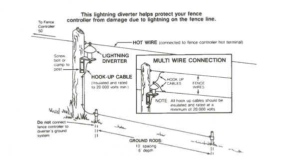
This lightning diverter helps protect your
fence controller from damage due to lightning on the fence line.
INSTALLATION
| 1.
|
For a single wire fence,
connect the lightning diverter to the fence wire before
mounting on to the fence post. Unscrew the top nut from
the lightning diverter, removing the washer and nut.
Position the lightning diverter against mounting post
with the fence wire passing through the split nut at the
top of the lightning diverter shield. Tighten the top
nut ensuring that the fence wire is not strained. Then
secure the lightning diverter to the fence post. |
| 2.
|
Where more than one
fence wire is hot, first mount the lightning diverter on
to the fence post before connecting hook up cables
(rated to 20,000 volts) to each of the hot wires using
line clamps. Unscrew the top nut and pass the hook up
wires through the split nut and tighten to secure. |
| 3.
|
Connect ground wire by
attaching hook up wire to bottom nut by winding in a
clockwise direction and securing nut. Attach other end
of hook up wire to ground system with ground clamps.
Diverter ground system should consist of a minimum of
two 6-ft. ground rods spaced 10 feet apart and 50 feet
from fence controller ground system. |
| 4.
|
For greater protection, install lightning
diverters on all corners of fence. First lightning
diverter should be installed no closer than 50 ft. from
fence controller.
|
VII.
HELPFUL
FENCE BUILDING HINTS
1) PERMANENT ELECTRIC FENCE
SPECIFICATIONS
| a.
|
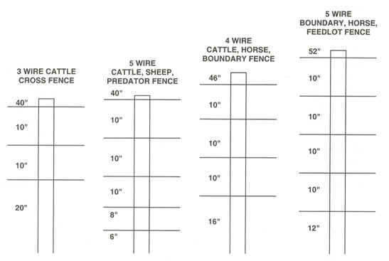
The number of wires and
the height of a permanent electric fence, aren't as
important as wire spacing. Wires should be spaced closer
together at the bottom of the fence, farther apart at
the top, so animals are shocked on the nose or front of
the head first. The following wire spaces were developed
over many years of trial and error.
As in portable electric fences, the
height of a permanent electric fence is less important
than the wire spacing. Most animals go under or through
permanent fences, rather than jump over them. |
| b.
|
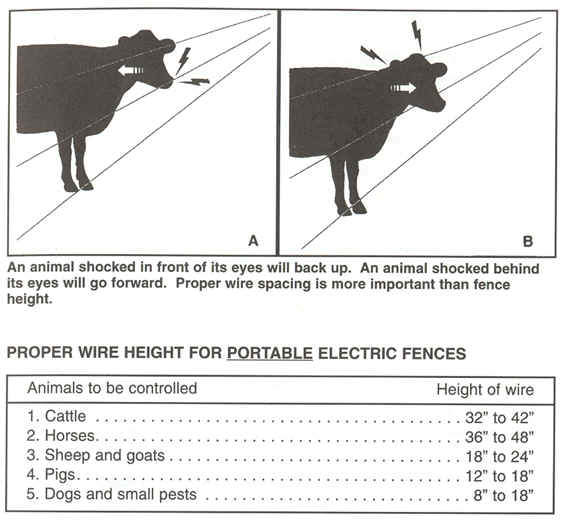
No matter how many
strands your fence has, one hot wire should be
positioned at shoulder height of the animal to be
controlled. This will cause the animal to hit the fence
with its nose first, the area most susceptible to
electric fence shock. If an animal is shocked in front
of its eyes, it will back up. An animal shocked behind
its eyes will go forward into the fence. Proper wire
spacing is more important than fence height. |
Since an electric fence isn't a physical barrier, the wire
doesn't have to be stretched (Piano String) tight. But, pull it
taut enough to stay at the same height between posts. Posts
should be spaced every 25 ft. to 75 ft., depending on the
terrain. If you space your post 75 ft. apart you should use
fiberglass battens to keep your wire spacing the same height
between the post.
Don't try to evenly space posts; in level terrain
posts can be spaced farther apart. In uneven terrain, posts need
to be spaced wherever there is a high or low place. On
hillsides, posts should be installed perpendicular to the slope.
This keeps the wire at the proper height and prevents it from
binding on insulators or clips.

|

![]()